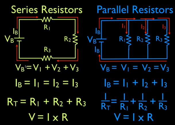

Since all of the current must pass through each resistor, it experiences the resistance of each, and resistances in series simply add up.Įxample 21.1 Calculating Resistance, Current, Voltage Drop, and Power Dissipation: Analysis of a Series Circuit This logic is valid in general for any number of resistors in series thus, the total resistance of a series connection isĪs proposed.

This implies that the total or equivalent series resistance of three resistors is. Note that for the equivalent single series resistance, we have Now substituting the values for the individual voltages gives (Note that the same amount ofĬharge passes through the battery and each resistor in a given amount of time, since there is no capacitance to store charge, there is no place for charge to leak, and charge is conserved.) The charge cancels, yielding, as stated. These energies must be equal, because there is no other source and no other destination for energy in the circuit. Involved in all electrical phenomena and will be invoked repeatedly to explain both specific effects and the general behavior of electricity. The derivations of the expressions for series and parallel resistance are based on the laws of conservation of energy and conservation of charge, which state that total charge and total energy are constant in any process. Is, while that dissipated by the resistors is Electrical potential energy can be described by the equation, where is the electric charge and is the voltage. This equation is based on the conservation of energy and conservation of charge. The sum of these voltages equals the voltage output of the source that is,

So the voltage drop across is, that across is, and that across is. Of this is that is the voltage necessary to make a current flow through a resistance. To verify that resistances in series do indeed add, let us consider the loss of electrical power, called a voltage drop, in each resistor in Figure 21.3.Īccording to Ohm’s law, the voltage drop,, across a resistor when a current flows through it is calculated using the equation, where equals the current in amps (A) and is the resistance in ohms. It could be a disadvantage if one of the resistances were a faulty high-resistance cord to anĪppliance that would reduce the operating current.)įigure 21.3 Three resistors connected in series to a battery (left) and the equivalent single or series resistance (right). (Thisįact would be an advantage to a person wishing to avoid an electrical shock, who could reduce the current by wearing high-resistance rubber-soled shoes.

It seems reasonable that the total resistance is the sum of the individual resistances, considering that the current has to pass through each resistor in sequence. For example, if current flows through a person holding a screwdriver and into the Earth, then in Figure 21.2(a)Ĭould be the resistance of the screwdriver’s shaft, the resistance of its handle, the person’s body resistance, and the resistance of her shoes.įigure 21.3 shows resistors in series connected to a voltage source. When are resistors in series? Resistors are in series whenever the flow of charge, called the current, must flow through devices sequentially. The total resistance of a combination of resistors depends on both their individual values and how they are connected.įigure 21.2 (a) A series connection of resistors. The simplest combinations of resistors are the series and parallel connections illustrated A measure of this limit on charge flow is called resistance. Most circuits have more than one component, called a resistor that limits the flow of charge in the circuit. Read this text, which implements this strategy, with the aid of two basic rules: one for series and one for parallel resistors. It does not matter whether several individual resistors exist between the two terminals in question, or just a single wire, as long as we know the resistance of our black box. And we can indeed treat complicated arrangements of resistors as a black box, so long as there are just two terminals connecting the black box to the outside (because resistors must have two terminals). You could say the idea behind analyzing circuits is to get as far as possible by treating parts of the circuit as a black box. All we really care about is the value of the resistance that needs to be plugged into Ohm's Law, as applied to the current and voltage found at the two terminals leading into and out of the resistor. We can do this because the internal details of a resistor are irrelevant to its function in a circuit. Just as with capacitors, we can simplify the analysis of a resistor circuit step-by-step, by imagining replacing a combination of resistors by a single (" effective") resistor. We can make the same two basic types of arrangement with resistors. We have already covered combinations of capacitors in series and parallel.


 0 kommentar(er)
